Sensor Board
The sensor board application is a simple flight computer for model rocketry.
AURORA is built to run on multiple interconnected PCBs that communicate over CAN
bus, i2c or other fieldbus technologies.
sensor_board manages the IMU and barometric sensor data, uses the flight state
machine, pyrotechnic ignition, hardware notification and data logging and is
designed to deploy a parachute when the model rocket reaches apogee.
Operating the Board in the Field
This section walks through what actually happens on the launch site, from the moment you flip the power switch to the moment you walk back from recovery. It is written for the person standing next to the rocket, not for the firmware developer. For the internals, see the sections further down.
What the board is telling you
The board talks to you through two channels: a buzzer and one or more status LEDs. There might be no screens on the launchrail, so it is worth getting used to both before the first real flight. The two backends signal the same flight states, so you can rely on whichever is more practical for the conditions (LED in a noisy crowd, buzzer once the rocket is out of sight).
Buzzer, in broad strokes:
Boot sound: short jingle the moment the board is powered on. If you don’t hear this, the board is not running.
Calibration-in-progress sound: plays while the board is collecting reference samples after you arm it. The rocket must stay still during this phase.
Calibration-finished sound: a single confirmation tone. The board is now ready for launch.
Landed song: a longer tune that loops after touchdown and keeps going until you disarm or power down. This is your recovery beacon and shall help you find the rocket in a corn-field or a difficult place.
Status LED, in broad strokes:
Boot flash: solid ON for half a second, then off. Pairs with the boot jingle and confirms the board has come up.
IDLE: short, sparse pulses (about twice a second). The rocket is disarmed and safe to handle.
ARMED: even, steady blink. Pyros are live. If you see this from the launchpad walk-back, the board is ready.
In-flight (BOOST through REDUNDANT): LED stays dark. This is intentional. It saves battery and avoids optical noise during flight.
LANDED: long pulses (mostly ON, brief OFF). Pairs with the landed song as a visual recovery beacon.
ERROR: solid ON without blinking. Service required.
Tip
The full pattern tables are in Buzzer Patterns and LED Patterns.
Note
The LED backend depends on the data logger being enabled. When the data logger is disabled, the LED stays dark. The buzzer is unaffected.
Step-by-step commissioning
The following sequence assumes a board that has already been built and flashed, with a charged battery and a µSD-card installed. Hardware-specific arming mechanisms (key switch, button, plug, …) differ per board. Check the board’s own page under Supported Boards for the physical detail.
Pre-flight check on the bench. Battery charged, µSD-card inserted, pyro channels wired but not yet connected to igniters. Confirm the rocket is in the disarmed state before going anywhere near the pad.
Place the rocket on the launchrail. Do this before arming. The board uses its first stable orientation as the reference for “vertical”, so any leaning or repositioning after arming will throw off the calibration. When you move the rocket in an armed state, make sure to disarm and rearm again when the rocket is in its final position before liftoff.
Power on. You should hear the boot sound and see the LED flash solid for about half a second, then drop into the slow IDLE blink. The board is now running but is still in the IDLE state. It will not react to motion yet.
Connect the igniters. Only do this with the board powered on but still disarmed, following your range’s safety procedure.
Arm the board. Trigger the arming mechanism (the exact action is board-specific). The board moves into the calibration phase and starts playing the calibration-in-progress sound.
Hold still. Don’t bump the rail, don’t walk into the rocket, don’t re-aim. Calibration only converges when the IMU is genuinely stationary.
Wait for the ready tone. Once you hear the calibration-finished sound and see the LED switch to the even ARMED blink, the board is armed and waiting for liftoff. You can now clear the pad.
Need to abort or re-aim? Disarm the board. It will return to IDLE. You can re-arm as many times as you like. The state machine just cycles back into calibration each time, which is by design. There is no “wasted” arming attempt.
Launch. The state machine takes over from here: BOOST, BURNOUT, APOGEE (drogue parachute deployment), descent, MAIN, REDUNDANT and finally LANDED. See the state machine diagram for the full transition graph.
Recovery. When the board detects landing, it starts playing the landed song and the LED switches to the long-pulse landed pattern. Walk in the direction of the sound; if it is a bright day, the LED can also help once you are within line of sight. Once you’ve found the rocket, disarm or power down the board to silence it.
Note
Usually it is not a problem, but removing the µSD card from the board should only be done when the board is disconnected from the battery.
Things that commonly go wrong
Calibration never finishes. The rocket is moving, wind on a tall rail is a common culprit. Disarm, wait for the rail to settle, re-arm.
Board disarms by itself. The rail is tilted past the disarm angle threshold (see Configuration below). Either re-aim the rail or relax the threshold for the campaign.
No landed song after recovery. Either the battery is empty, the µSD card filled up mid-flight and the board faulted, or the landing was not detected (e.g. it is still drifting under canopy in a tree). Check power and the data log before assuming a software issue.
LED stays solid ON without blinking. That’s the ERROR pattern, not a ready indicator. The board has hit an unrecoverable fault. Power down, pull the µSD card, and check the log before flying.
LED never lights up at all. The LED backend depends on the data logger; if the logger is disabled (or failed to mount the µSD card), the LED stays dark even though the rest of the board is fine. Listen to the buzzer to confirm flight state in that case.
Techical Aspects
Sensor Data Path
It’s a tricky situation trying to fetch data from all sensors at the exact same time and passing them on to the state machine, the state machine filter and the data logger. Here is a rough overview of how AURORA’s data is passed between threads to the state machine and the data logger:

Threads
sensor_board uses up to three additional Zephyr threads
(all priority 5, 2 KB stack):
Thread |
Guard |
Purpose |
|---|---|---|
|
|
Polls IMU at the configured frequency, updates orientation and acceleration globals. |
|
|
Measures pressure/temperature, computes altitude. |
|
|
Runs at 10 Hz. Feeds sensor data into the state machine and fires pyro channels on state transitions. |
When sensors are configured to use active polling, baro_task and imu_task
run the whole lifetime of the application.
When baro, imu or both are using interrupt triggers, baro_task and imu_task
complete after initialisation and the generic sensor trigger threads are
running.
Note
To get an overview of running threads, use the Zephyr-Shell builtin command
kernel threads list.
Configuration
State Machine Thresholds
These options are defined in sensor_board/Kconfig under the
State Machine Configuration menu.
Flight Thresholds
Option |
Unit |
Default |
Description |
|---|---|---|---|
|
m/s² |
30 |
Acceleration threshold for boost detection (ARMED -> BOOST). |
|
m |
50 |
Altitude threshold for boost detection (ARMED -> BOOST). |
|
m/s² |
15 |
Acceleration threshold for burnout detection (BOOST -> BURNOUT). |
|
m |
200 |
Descent altitude for main pyro event (APOGEE -> MAIN). |
|
m/s |
2 |
Velocity threshold for landing detection. |
|
deg |
85 |
Orientation threshold for arming (IDLE -> ARMED). 0 = horizontal, 90 = vertical. |
|
deg |
70 |
Orientation threshold for disarming (ARMED -> IDLE). |
|
n |
10 |
Number of consecutive samples for disarming (ARMED -> IDLE). |
Timers and Timeouts
Option |
Unit |
Default |
Description |
|---|---|---|---|
|
ms |
900 |
Duration that boost thresholds must be held before transitioning. |
|
ms |
500 |
Duration that landing velocity must be held. |
|
ms |
60000 |
Max time in APOGEE state before aborting to ERROR. |
|
ms |
2000 |
Delay between MAIN and REDUNDANT pyro events. |
|
ms |
900000 |
Max time in REDUNDANT state before aborting. |
Application Simulation
When built with CONFIG_AURORA_FAKE_SENSORS=y (typically together with the
native_sim board target), sensor_board replaces the real IMU and baro
polling threads with a synthetic data source. The fake threads publish on
the same zbus channels (imu_data_chan, baro_data_chan) at the same
cadence as the real drivers, so the state machine, filter, data logger and
pyro logic run unchanged.
Two backends sit behind the same shell interface:
Backend |
Kconfig |
Source of samples |
|---|---|---|
Synthetic profile |
|
Analytic ISA-troposphere flight profile generated on the fly. |
Replay |
|
Samples from a recorded |
Synthetic profile
The default profile follows an ISA-troposphere altitude/pressure curve with
a constant-thrust boost phase, a ballistic coast to apogee and a
constant-rate parachute descent. It is controlled from the Zephyr shell via
the sim command group:
Command |
Description |
|---|---|
|
Start the synthetic flight profile. The uptime at which this command is issued is used as t=0. |
|
Return the profile to pad-stationary (altitude 0, accel = +g on the vertical axis). |
|
Print the current flight time, altitude (m) and vertical proper-acceleration (m/s²), or |
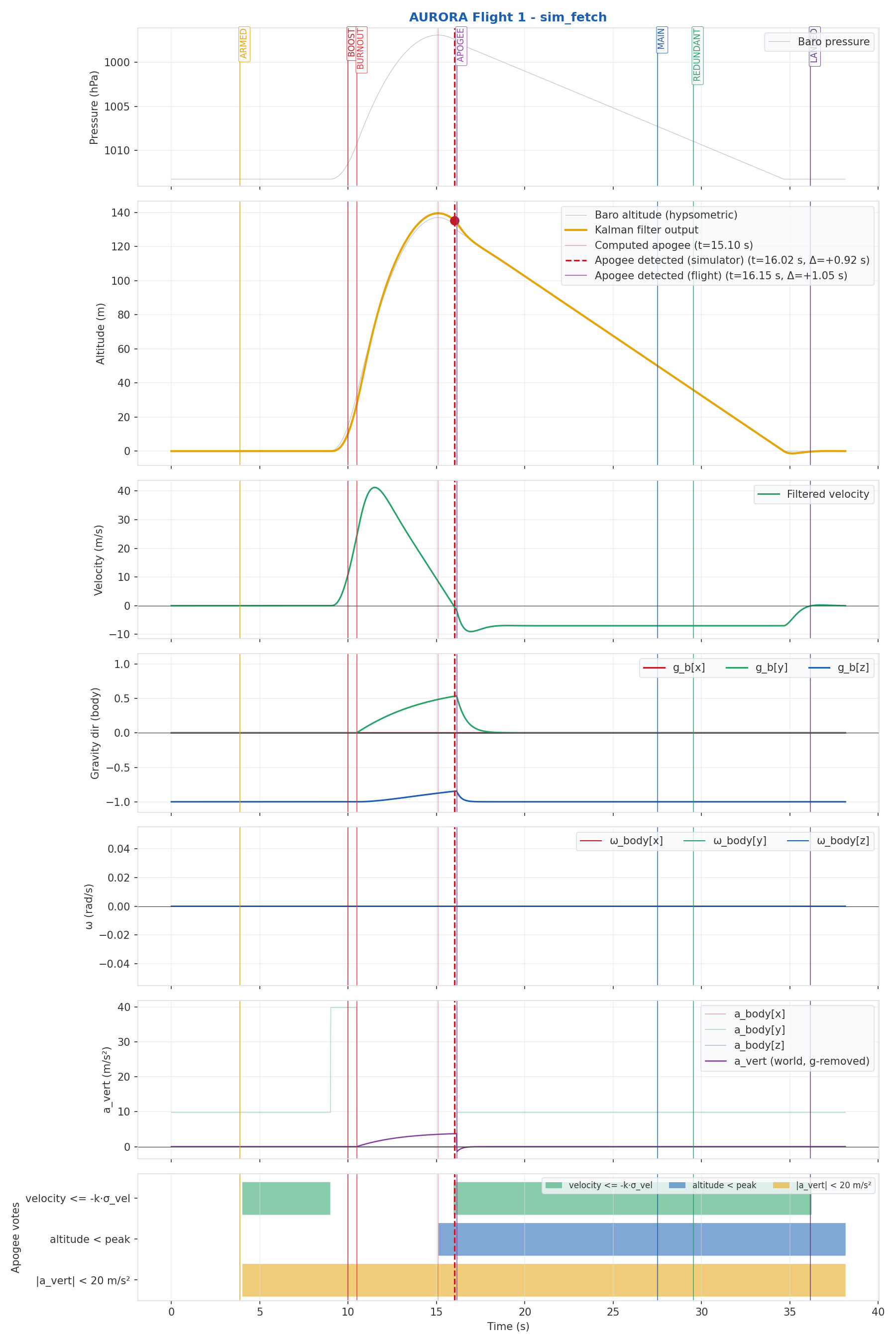
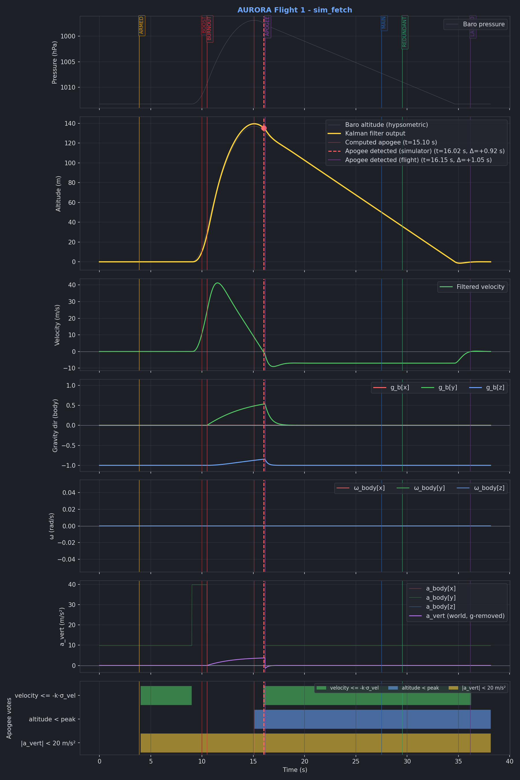
Using the native_sim board target, and the
sim_fetch.py tool, it is possible to run application
simulations and create graphs from the data_logger output:
Replay backend
Setting CONFIG_AURORA_FAKE_SENSORS_REPLAY=y swaps the analytic profile
for a playback engine that streams a previously recorded flight back into
the system at the original cadence. The samples are baked into the
firmware image at build time, so no filesystem or network access is needed
at runtime. Useful for CI runs and for regression-testing the Kalman
filter / state machine against known-good data.
The recording is selected via:
CONFIG_AURORA_FAKE_SENSORS_REPLAY_INPUT="flight_logs/<campaign>/<flight>/flights.csv"
(Paths are relative to the aurora module root.) During the build, the
gen_flight_replay.py tool turns the CSV,
and (if a sibling state_audit file is present) the trimmed
[BOOST - 4 s, LANDED + 4 s] window, into a generated replay_data.c
that is linked into the firmware.
Before launch, the replay threads keep the rocket “pad-stationary” by
republishing the very first recorded sample, so attitude calibration
converges as it would on the real hardware. Issuing sim launch from the
shell (or letting CONFIG_AURORA_SIM_AUTOTEST=y do it automatically) then
starts the playback.
Supported Boards and Shields
Since sensor_board is an auxspace internal project, only auxspace hardware
is tested with the application.
Sensor Board v2 - RP2040 / RP2350 flight computer
ESP32-S3 Micrometer - ESP32-S3 based board
Hardware Requirements
Any board that wants to run sensor_board has to provide the following
peripherals and wire them up via Zephyr chosen nodes. The chosen-node
names below are what the application looks up at boot. If a node is missing
the corresponding feature is silently disabled (or the build fails, in the
case of the sensors).
Requirement |
Chosen node |
Notes |
|---|---|---|
IMU |
|
6-DoF accelerometer + gyro. Needs at least >=100 Hz ODR to catch boost cleanly. Tested with LSM6DSO32. |
Barometric sensor |
|
Absolute pressure sensor for altitude. Tested with MS5607 and LPS22HH. |
Storage device |
|
µSD-Card or eMMC, at least 16 GiB. Flight computers often have no on-board storage, so an external card is required. |
FAT filesystem |
|
A |
Flight-log raw region |
|
A reserved raw region on the same storage device used by the data logger for high-rate writes. Needs ≥7 GiB (see the storage-access pattern caveats). |
Pyro driver |
|
At least two pyro channels (drogue/main) plus a redundant channel if you want the |
Battery |
- |
Sized for at least the longest realistic flight + recovery window. The |
PWM buzzer (optional) |
|
Passive buzzer driven via PWM. Used for boot, calibration, state-change and recovery cues. Optional - board still flies without it, but you lose the auditory cues. |
Status LED(s) (optional) |
|
One or more LEDs as children of a |
Arm/disarm input (optional) |
|
A GPIO-backed switch, button or magnetic key that asserts the ARM signal. Mechanism is up to the board: the application only sees an edge. Optional - not implementing this feature might cause problems when the board is only armed and disarmed via orientation. |
Fieldbus (optional) |
- |
CAN, \(I^2C\) or similar, if the board is part of a multi-PCB AURORA stack. Not required for a standalone flight. |
Warning
µSD cards that do not contain a flight log will be formatted by the firmware. All previous data will be lost.